For education#
In the last year of my degree, I was introduced to modern control systems. Naturally, courses have to be rushed to get through as much of the content as possible; I wasn’t satisfied with my understanding of the material. Over the summer of 2024 to 2025, I decided to work on a project that would improve my understanding of linear control systems, or at least give me a platform that I could experiment with. A balancing apparatus would be perfect as a project. In fact, one of the most common control systems projects is a linear inverted pendulum:

A cart is moved in one axis to balance a pendulum vertically. This is similar to balancing a pencil vertically on your finger. But given that my workspace is small and the linear inverted pendulum requires many more parts, a rotary inverted pendulum was more appropriate:

Unlike the linear variant, a rotary inverted pendulum rotates the base instead of moving it horizontally, making it much more compact. No need for pulleys, chassis or extra space. The base can be simply rotated directly via a motor or through gearing.
Demonstration#
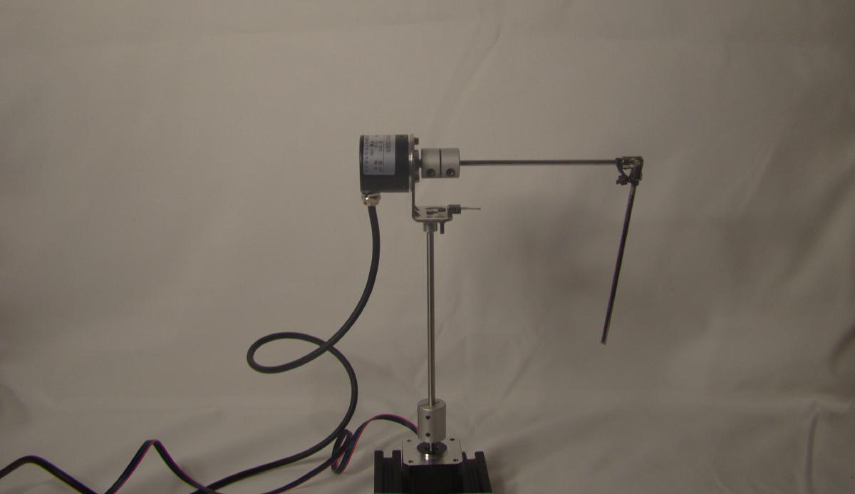
The mechanical side of the build is simple. A motor drives a vertical shaft connected to a flange, which then links to a horizontal shaft and the pendulum:

The rig needs a rigid 90 degree connection between the horizontal shaft and the pendulum. Since I couldn’t find a shaft with a fixed right-angle bend, I used a universal joint coupler instead:

These couplers are free to swivel as they rotate, which would cause the pendulum to bend in this manner:

This is undesirable, so I ziptied the pendulum and horizontal shaft together.
Regarding the electronics, I used a stepper motor driven by a stepper driver. An Arduino Uno controls the stepper driver and processes the control algorithm. In addition, the rotary encoder is read directly by the Arduino Uno.
Bill of Materials#
The total cost of the project, including electronics, summed to 142.44 NZD.
Mechanical#
| Item | Quantity | Cost (NZD) | Source |
|---|---|---|---|
| Linear Shaft, 150mm length, 5mm diameter | 1 | $4.17 | Aliexpress |
| Rigid Shaft Coupler, 5mm to 5mm | 1 | $4.79 | Aliexpress |
| Rigid Shaft Coupler, 4mm to 6mm | 1 | $4.46 | Aliexpress |
| Universal Shaft Joint Coupler, 4mm to 4mm | 1 | $3.53 | Aliexpress |
| Rotary Encoder Mounting Bracket | 1 | $27.74 | Aliexpress |
| Linear Shaft, 125mm length, 4mm diameter | 2 (from 5pcs set) | $7.36 | Aliexpress |
| Rigid Flange Coupler, 5mm | 1 (from 3pcs set) | $14.94 | BigFace |
Electronics#
| Item | Quantity | Cost (NZD) | Source |
|---|---|---|---|
| Incremental Rotary Encoder 38S6G5-B-G24N 1000ppr | 1 | $26.34 | Aliexpress |
| Stepper Motor Nema 17 17HE19-2004S | 1 | $27.41 | Aliexpress |
| Stepper Motor Driver TMC2209 | 1 | $5.87 | Aliexpress 1 |
| Arduino Uno | 1 | $20 | ? 2 |
Notes#
- I couldn't get the UART communication working but the STEP/DIR functionality worked just fine, which is all I needed.
- I reused an Arduino Uno I bought a long time ago, so the price is estimated.